MX-AN01: The Versatile Analog Interface
Board for T100MX

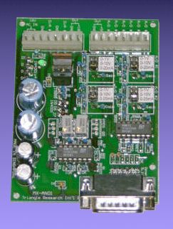
The MX-AN01 board is a
multi-purpose Analog Interface Board specifically designed to be connected to
the T100MX Programmable Controller via a straight DB15 cable. The analog Inputs
and Outputs signals as well as power supply leads are available on 2 units of
8-pin 0.156" center headers. Crimp terminal pins and terminal housing are
provided for connecting the required signals to the MX-AN01 board.
Note: T100MD-1616
does not require MX-AN01 as the same circuitry has already been built-in
Figure 1
Power Supply
MX-AN01 requires only a
cheap 18V AC transformer with at least 0.3A current capacity to the terminal
marked "18V AC IN " near the bottom edge of the circuit board. A green
power LED will light up when the AC power is turned ON. The power supply circuit
produces two regulated voltages: an 18V DC (± 5%) and a 5V DC (± 1%). Both
voltages are made available for external use at the header as shown in Figure 1.
The maximum total (+18V and +5V) allowable load current should be restricted to
below 0.2A. These voltages can be used to supply power to industrial analog
sensors and signal conditioners.
Please make sure
that you turn OFF all power before connecting any wire or the DB15
connector to T100MX. "Hot-plugging" when power is ON can cause
permanent damage to T100MX main CPU, resulting in expensive repair!
Analog Inputs A/D #1, #2, #3 and #4
Each of these four Analog
input ports is jumper selectable to accept 0-1V, 0-10V or 0-20mA current loop
signals produced by industrial sensors or instrument. (4-20mA signals can also
be accepted by treating them as a subset of 0-20mA). Before connecting the
external analog signal, place the jumper blocks for the channel in the correct
location according to the type of analog signal as shown in the following
figure:
The analog signal
can then be connected to the respective header pin as shown in Figure 1. Note
that analog signals of other voltage range types, e.g. 0-3V, 0-5V etc can also
interface to these four inputs by using two external resistors to form a voltage
divider to divide the analog signal to 0-1V range and then configure the input
as 0-1V range.
If the sensor has
its own power supply then you must connect the sensor "ground" to any
one of the "GND" signals on the MX-AN01 board to provide a common
ground. Unconnected analog channel #1 to #4 should not be configured for 0-1V
because the op-amp will have a floating input that will drive it to saturation,
causing excessive heating.
Note:
Very weak signals (m V range) such that those produced by thermo-couple
require special "signal conditioners" to amplify the signal to
either 0-10V or 0-20mA for interface to MX-AN01. Signal conditioners may be
purchased separately from the suppliers of analog sensors. MX-AN01 is not
designed to handle such weak signals which require very special treatment to
take care of common mode noise that can overwhelm the signal.
Analog Inputs A/D #5, #6
Each of these two analog input
ports is connected via a resistor and Zener diode protection circuit to the A/D
input pins of T100MX. Hence it can only handle 0-5V type analog signal. These
two analog inputs can be conveniently used with a 1K potentiometers and the 5V
power supply outputs from the MX-AN01 to form a simple low cost input devices as
shown in the following diagram:
Such input devices can be
used to set some operational parameters such as desired temperature, volume
control, or even joystick for motion control, etc. It is up to the user’s
program to take advantage of this low cost user interface.
Analog Outputs D/A #1, #2
The 0-5V D/A output signal from
T100MX is converted to 0-20mA current loop on the MX-AN01. This interface is
also compatible with the popular industrial analog voltage of 4-20mA, simply by
adding an offset value of (1/5 of 4096 =) 819 to the SETDAC parameters. The
schematic diagram of the 0-20mA converter is as follow:
Current loop output
has the advantage over voltage output especially for long distance applications
because the signal would not be diminished by the resistance of the wire. In
addition, current loop interfaces are not susceptible to induced voltages along
the signal wire.
The 0-20mA current loop output is powered
by the MX-AN01’s built-in power supply. Note that the D/A circuit works by
controlling the output voltage until it achieve the desired current. When the
loop is opened (not connected to the load) the output will be driving at its
maximum voltage (known as the output compliance) The compliance is about 16V for
MX-AN01. Hence the maximum allowable load resistance should be less than
16/20x10-3 = 800W .
To use the current loop output, simply
connect the D/A output and the GND terminals to the target load. The output can
be calibrated using the on-board trim-pot - simply run the SETDAC 1,2048 command
and adjust the trim-pot until the current output records a 10mA reading on a
precision ammeter.
0-5V or 0-10V D/A outputs
It is a simple matter to convert
a current loop output to a voltage output by connecting a resistor across the
output terminals. Hence to achieve 0-5V, connect a 250W resistor, and to achieve
0-10V, connect a 500W resistor. For loads located at a long distance from the
controller, you can take advantage of the current loop interface by connecting
the resistor at the load end, as follow:
This method will
only work if the target analog load is of sufficiently high input impedance
(most are) which means the current drawn by the input is negligible. If there is
a need to parallel the output to more than one device, then only one resistor is
used. You can also add a voltage follower circuit as follows to convert the
output to true voltage output: